The DS3231 is a real time clock utilized by the arduino micro-controller to remember and to trigger time based events. It features a CR2032 coin-cell backup battery pack, which will keep it powered for long periods of time when micro-controller power has failed by only powering the chip tasked with time keeping. During this power failure, the red LED which would normally be illuminated will be off during this time. Due to the various settings the module can be deployed it has a temperature-compensating chip that varies the oscillation cycle to adjust for high heat and cold. This unit retails on Amazon at 2 for $6.99 and is very easy to manipulate in the Arduino IDE.
Required Materials:
DS3231 RGB Led (Common Cathode) Jumper Wires
Breadboard 100Ω Resistor (x2) Micro-controller
Next we need to download the operating code from the GitHub repository.
Now scroll to the green “Clone or download” button and select the “Download Zip” option and save to the desired destination.
Next, open the Arduino IDE and navigate to Sketch> Include Library> Add .ZIP library and find the Zip file you just downloaded and you’ve successfully installed the code to your IDE.
From your Zip file, select RTClib.zip\RTClib-master\examples\ds3231 and save it to your main Arduino file.
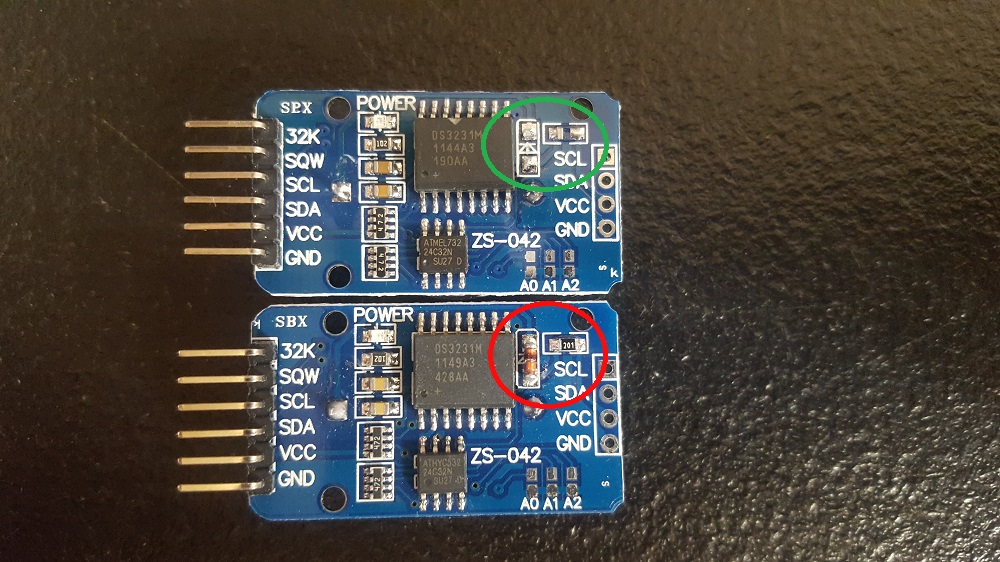
Next, you must desolder components seen in the red circle below. The default configuration of the DS3231 is to use the backup battery when not connected to main power and to use main power when its connected to it. Along with using main power, the DS3231 diverts some of the power back into the coin cell battery to try and recharge it, which is a good idea in theory. The fatal flaw is that the batteries used aren’t rechargeable, which creates a fire hazard if you connect it long enough as it is possible for it to explode. Use a soldering iron to remove the components circled in red and you effectively mitigate your chances of having an exploding battery.
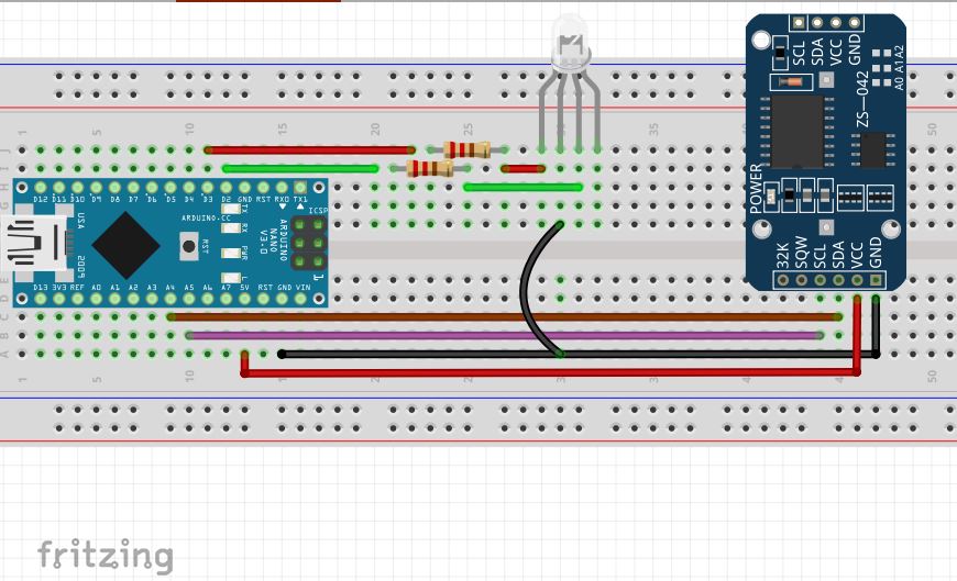
Using the Fritzing sketch below, hook up your unit as follows, ensuring the battery is removed.
Open the IDE saved earlier and in your pre-setup section paste the following:
Notice that in the loop section of the code now.year/month/day/hour/minute/second is now represented by currentYear/Months/Day/Hour/Minute/Second. You can adjust the text left of the equals (=) sign to any letter or numeric value as long as you define it in the pre-setup section as int (Random Numeric or letter value);. Once complete, we must identify the start time when DS3231 power is cycled by editing line 37 to about ten minutes ahead of the current time and adjusting the date to the current year, month, and day.
Next, verify you’re using the correct COM Port, programmer, board type & processor then upload. After uploading, wait until you’re about 15 seconds from the target time set by the adjusted code & cycle the power, turning it off then back on & open the serial monitor. Once everything starts up you should see the current time displayed with it only being a few seconds off, which is okay. Now we’ll run a timing experiment by going into the pre-setup section & inserting the following code:
int greenLed= 2;
int redLed= 3;
In your setup code insert the following:
pinMode(greenLed, OUTPUT);
pinMode(redLed, OUTPUT);
and at the bottom of your loop section insert the following:
If (currentSecond>=15 & currentSecond<=30 ||
currentSecond>=45 & currentSecond<=59){
digitalWrite(redLed, HIGH);
digitalWrite(greenLed, LOW);
}else{
digitalWrite(greenLed, HIGH);
digitalWrite(redLed, LOW);
}
}
The inserted code is saying if the time is between 15-30 or 45-59 to activate the red light, if not activate the green light. If everything is wired according to the Fritzing sketch then it should work properly.
Note: For reference, the <,>,<=,>=, symbols mean less than, greater than, less than or equal to, and greater than or equal to respectively. The || symbol are called pipes and are found by pressing shift & the key right above the enter key. These pipes represent ‘or’, giving a range of choices for the micro-controller to select from. Experiment complete.