The ATMega328p is a micro controller used by the company Arduino to complete tasks via the Arduino IDE, an integrated development environment that writes and tests software generated by the user. The term ATMega and Arduino are terms that will be used extensively in this site as a reference to the ATMega328p as many call it the Arduino chip and I personally know it as the ATMega chip. In this article I’ll explain what you need to be successfully implement Arduinos in your projects by explaining the unit, the IDE, as well as good gee whiz information that’ll make life that much easier for you.
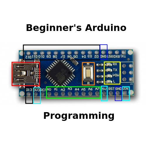
GPIO Pins
Black Group- Digital Pins
Green Group- Analog Pins
Digital Pins
There are a total of 13 digital pins capable of supplying or removing power to sensors & other units requiring electricity. What makes these pins digital is that they are either on or off (also known as HIGH or LOW when coding) and have no range to them as analog pins do. They are similar to analog pins in that they’re able to detect (digitalRead) or supply (digitalWrite) electricity as long as the required current per pin is below 20 mA & the required voltage is at or below 5v.
PWM Pins
Also known as Pulse Width Modulation, pwn pins are a modified fusion of digital & analog pins being that they can send digital (high or low) or analog (analogWrite(0-1025)) electricity where 0-1025 represents a range of 0-5 volts of electricity respectively. The arduino can also complete a digitalRead to detect if a pin is low or high (if there is electricity or not).
PWM Example:
Analog Pins
Analog pins can read or write modified electrical signals coming from units such as potentiometers or other sensors. There are a total of 8 pins (where zero counts as one) with four of them being specialized pins. Analog pins A4 & A5 are used in I2C communication & A6 & A7 are only used to read analog signals
Arduino Purchase
If you’re looking for affordability and don’t care about supporting a generic brand, I suggest you use the Elegoo brand Arduino family such as the Elegoo nano and Elegoo uno, which are non-sponsored products costing thirteen dollars for three and twelve dollars respectively. I suggest hobbyists use them in place of the official Arduino Uno/ Arduino Nano, which costs twenty and twenty-two dollars for one unit. Despite understanding the need for helping the Arduino company as they assist in the research and release of more products, I also refuse to spend twenty plus dollars on a unit for each individual project I make. Doing so would require I spend upwards of two hundred dollars on the micro controllers alone, something I absolutely refuse to do.
Software Installation/ IDE Setup
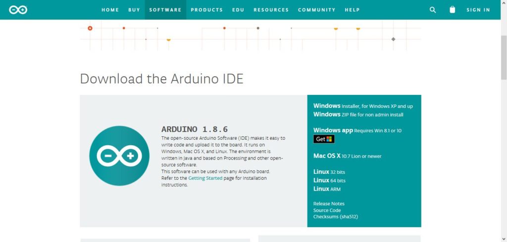
Upon purchasing and receiving your micro controller, the next step is to navigate to the arduino website to download the IDE, which will program you chips. Execute the following steps to get everything set up:
1. Go to the Arduino website and select the installer for your computer & download.
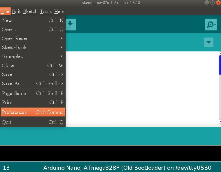
2. Navigating To Preferences While in the IDE navigate to File>Preferences to edit the default location of your sketches by selecting the ‘Browse’ button next to the ‘Sketchbook Location’ text box. Click the Navigating To Preferences (Detailed) drop down below for a detailed explanation on advised settings to select.
1. Click File>Preferences to adjust default settings of the arduino IDE
2. Select the check-boxes on your IDE as seen in the below picture.
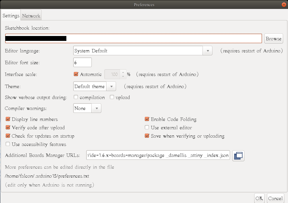
Preferences Points of Focus:
Display Line Numbers- Useful when maintaining notes on what line numbers need to be edited.
Verify Code After Upload- Double checks your work to ensure there aren’t any errors
Check For Updates On Startup- Ensures you’re working with the most up to date libraries, codes, & examples.
Enable Code Folding- Exponentially increases proficiency as you can fold away pieces of code that doesn’t require editing.
Save When Verifying or Uploading- Ensures you don’t lose your work after editing & upload.
3. Upon opening the sketch you will see the following sketch appear, except with void setup starting on line one. I’ve spaced it down a few lines as you will need the white space to code.
![]()
4. In general, there are three sections of the IDE, the pre-setup section, setup section, and the loop section. The pre-setup section is where you identify your pins as seen below as ‘int greenLed= 3;’ when identifying a pin, the ‘int’ refers to integer, which includes a number range between -32,768 to 32,767. More information on different data types as well as when/ where to use them can be found here. The ‘greenLed’ is the custom name I’ve made to represent digital pin three, and you can name your pins whatever you want; however, if you’re custom name changes colors then you need to change it as the IDE has identified it as a reserved word. Reserved words are key phrases that tell the IDE to prepare for a specific set of data or to prepare to do an action. Using reserved words as a named variable will grant you errors & improperly processed code. Last is your semicolon ‘;’ which is required for nearly every data type id except for in cases such as ‘define‘ & ‘include‘, which results in a cryptic error if you insert a semicolon as it doesn’t require semicolons.
5. The setup is where you identify if your pin is an input or an output. Notice that pin mode is typed with the ‘m’ capitalized. The rule is to capitalize any second word typed in the IDE when its used as a reference such as pinMode or digitalWrite in the loop section. Not doing this will throw an error requiring adjustment to operate properly. Outputs and inputs are always capitalized, with inputs identifying pins to receive data and outputs sending data. The setup section is only run once by the ATMega, meaning that a fully assembled project could be coded to run a short function test proving that all parts work correctly.
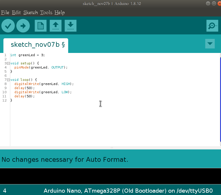
6. The loop section is run indefinitely and is where the real action occurs. In the sketch above I have an led flashing every 50 milliseconds to prove it works properly, but you can setup the program to be a lot more complicated than what’s presented here.
7.
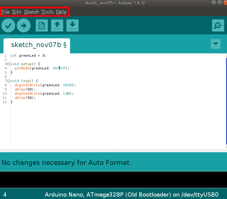
The red highlighted section shows the tabs you’ll be using when editing & verifying the code. I’ll only be covering sections requiring explanation & ignoring the more obvious descriptors such as what saving does.
File Tab:
> Examples> Built-In Examples- Gives a series of basic tutorials on coding techniques & projects you can experiment with.
>Preferences- Adjust IDE settings
(Edit Tab Has No Necessary Sub-sections)
Sketch Tab:
> Include Library> Add .zip library- Allows the programmer to include libraries for sensors & algorithms for additional arduino functionality
8. You need the following to make your physical connections: 100Ω Resistor, single color led, micro controller, usb cord, jumper wires, & breadboard. Connect them as seen in the figure below & you’re set!