Required Items:
Relay Phillips Head Screwdriver
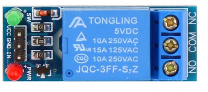
The picture below is that of a mechanical relay, which is used to enable/disable a connecting circuit such as a light bulb, pump, or motor. The male headers on the right connect to your arduino by connecting relay VCC>arduino 5v, GND>GND, IN> Any digital or analog pin of the arduino. For this example we’re going to connect the IN to arduino digital pin 2 and have no load connected to the NO/COM/NC terminals.
These terminals represent normally open (normally disabled), common (can be VCC or ground, one or the other), and normally closed (normally enabled) respectively. When the relay is activated it will always do the opposite of the terminal its connected to. An example would be if you connect to COM and NO (normally open), the circuit would be off when not activated, when activated a green light would turn on and the circuit will close, enabling the load.
Relay Sketch:
The above sketch is different from most in that it begins with the relay being sent a LOW signal. Typically a LOW signal means something is turned off while a HIGH means something is turned on. Relays are different in that they’re enabled when sent a LOW signal and disabled when sent a HIGH signal, meaning LOW=On & HIGH= Off. It can be confusing, but is easy to navigate since you are aware of them being a special case.
Upon uploading the code, the relay will turn on/off on a one second cycle, which is adjustable by changing the delay. Note that the number in the parenthesis are milliseconds and not seconds, so 1 second = 10000 milliseconds.