The blink sketch is the most beginner friendly project in that it teaches you how to dictate which pins are to activate and the duration of said activation. In this project we’ll be activating a light emitting diode (LED) and adjust its flash duration using the delay(x); function, where x is the amount of milliseconds the LED will light up.
Required Items:
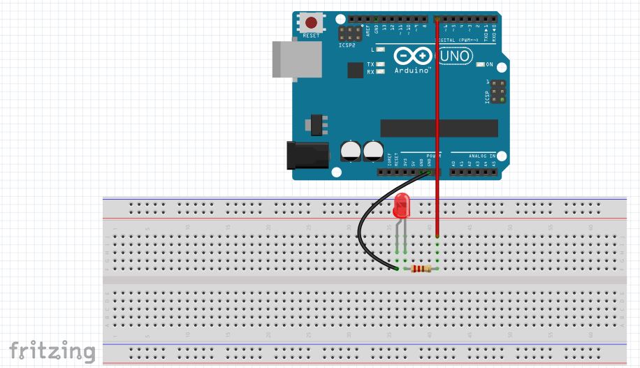
RGB LED (Common Ground) 100Ω Resistor
Fritzing Sketch:
Upon opening the sketch you will see the following sketch appear, except with void setup starting on line one. I’ve spaced it down a few lines as you will need the white space to code.
![]()
In general, there are three sections of the IDE, the pre-setup section, setup section, and the loop section. The pre-setup section is where you identify your pins as seen below as ‘int green led= 3;’ when identifying a pin, the ‘int’ refers to integer, which includes a number range between -32,768 to 32,767. More information on different data types as well as when/ where to use them can be found here. The ‘greenled’ is the custom name I’ve made to represent digital pin three, and you can name your pins whatever you want; however, if you’re custom name changes colors then you need to change it as the IDE will believe its data type references something you didn’t mean for it to represent. Last is your semicolon ‘;’ which is required for nearly every data type id except for ‘define‘ & ‘include‘, which results in a cryptic error if you insert a semicolon.
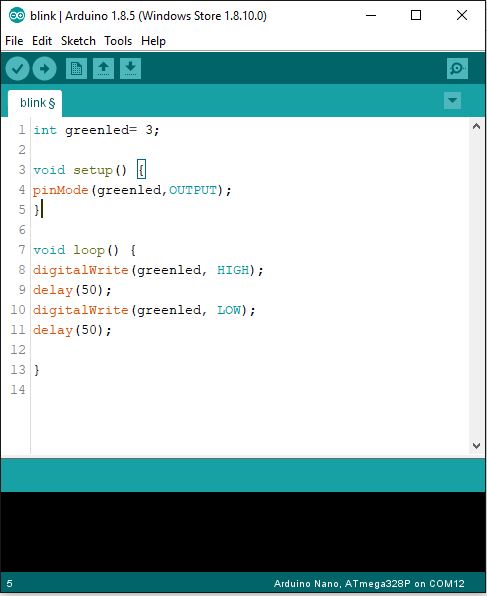
The setup is where you identify if your pin is an input or an output. Notice that pin mode is typed with the ‘m’ capitalized. The rule is to capitalize any second word typed in the IDE when its used as a reference such as pinMode or digitalWrite in the loop section. Not doing this will throw an error that will need a fixing to operate properly. Outputs and inputs are always capitalized, with inputs identifying pins to receive data and outputs sending data. The setup section is only run once by the ATMega, meaning that a fully assembled project could be coded to run a short function test proving that all parts work correctly.
The loop section is run indefinitely and is where the real action occurs. In the sketch above I have an led flashing every 50 milliseconds to prove it works properly, but you can setup the program to be a lot more complicated than what’s presented here.
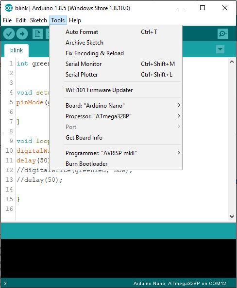
There are several things to mention at this point in the coding process. First are the verify and upload buttons, featured as the check mark and arrow symbol respectively. Verifying the code is valid can be done without delay, but hold off on uploading to your ATMega. Before uploading, go to the Tools section and check that you’re using the correct board, processor, port & programmer. If you’ve purchased the Arduino/Elegoo Nano or Uno then the board to select is self explanatory. However, if you’ve made an ATMega rig then you must select the ‘Arduino Duemilanove or Diecimila’ option. The processor is typically the ‘ATMega328P’ and programmer being the ‘AVRISP mkII’. The port number depends on what USB port you’ve connected to the micro controller, but can easily be identified if you only have one micro controller connected. Once you’ve done all that you’re free to upload the code…after you’ve made your physical connections.