Building arduino projects are a fun & informative way to learn more about programming & gives the user skills in hobby level home automation and project management. From autonomous drones to a garden watering circuit, the complexity of projects is incredibly vast. But with only 13 digital pins & 5 analog pins, what are you to do when you don’t have enough pins for your arduino? Simple, use the MCP23017 & the CD74HC4067.
Analog Mux Digital Mux Digital Mux Adapter
Mux is short for multiplexer, & is what’s used to increase arduino port availability. With the digital mux being so much less expensive than the analog, my first thought was to use the digital mux for both, to no avail. Despite this, I encourage you use the mux in place of simply using two arduino circuits as its better to use an item specific to your needs as an additional arduino only gives you 4 additional analog pins & 13 digital pins.
The MCP23017
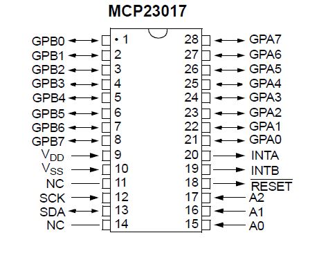
Below is a diagram of the digital port expander, which uses the I²C protocol, which only requires the A4, A5, VCC & ground pins to properly operate. The top of the diagram has a small half circle that denotes the top orientation of the IC to ensure there’s no confusion during pin hookup. Use this as a reference for all projects as all IC’s have either this semi circle or a dot denoting proper orientation. The 16 GPIO (General Input/Output) pins go from 0-15 and starts at pin GPA0, goes up to GPA7, crosses over to GPB0 (which is pin 8 when addressing it in the Arduino IDE), & goes down to GPB7. Use the picture as a guide when making your connections as its very easy to connect a pin to an incorrect chip position.
1. Digital MUX Library Download & Test
We’ll first download the following library for the digital Mux and point to it in the IDE by selecting Sketch>Include Library> Add .ZIP library
Private File - Access Forbidden
Once you have the library pointed to in the IDE, go to where you typically save you sketches and open up the .ZIP folder and navigate to Digital_Multiplexer.zip>Digital_Multiplexer>examples & save the dmuxInput & dmuxOutput sketches outside the .Zip folder. Once everything is saved we’ll move to setting up the example by setting up the following:
 .
.
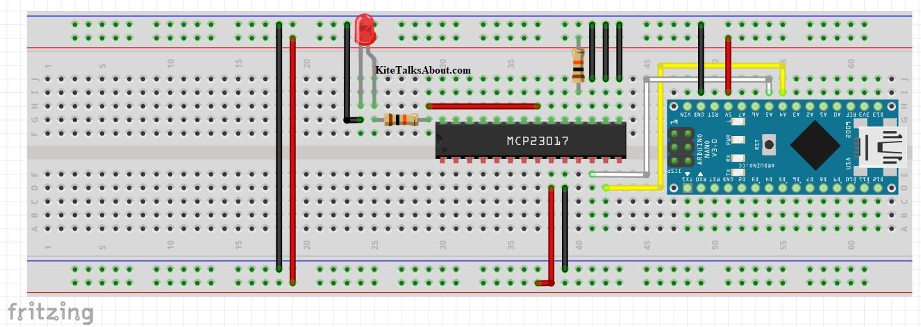
For quick reference, let’s use the table below in conjunction with the previously mentioned chip diagram, remembering to have a pin from pin #21 to the 10K resistor connecting to the longer positive leg of the LED.
| Digital Pin Out | |
|---|---|
| Digital Pin | Arduino Pin |
| 12, 13 | A5, A4 |
| 10,15-17 | GND |
| 9 | 5V |
| 18 | 10K Resistor to 5v |
Once everything is connected, upload the code in dMuxOutput, select you port, board, processor, then upload. If done correctly your led will illuminate every 2.5 seconds & deactivate every second. Now that we’ve verified its completion, we’ll move onto the input section and upload the sketch to the microcontroller. Connect expander pin #0 to 5v & expander pin #1 to the 10K Ω resistor notice how the led flashes. Remove the wire from pin #0 & the LED will stop blinking, proving the setup works!
2. Digital MUX Library Download & Test
Last is the analog mux, which functions similarly to the digital mux except for it being able to read numerical values.
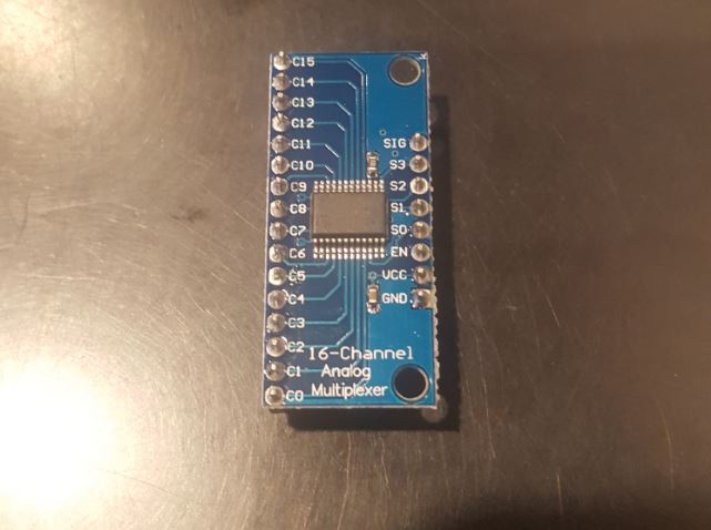
With the analog mux having all pins labeled, there’s no need to have any diagrams as everything is self explanatory. The pin out chart below explains where each pin connects & is simpler than the digital mux since most pins connect to ground. Strangely, the S0-S3 pins just needs to connect to arduino pins D8-D11, nothing else must be done, even in the software aspect, something I’ve never seen before.
| Analog Pin Out | |
|---|---|
| Analog Pins | Arduino Pin |
| GND | GND |
| VCC | 5V |
| EN | GND |
| S0-S3 | D8-D11 |
| SIG | A0 |
Private File - Access Forbidden
The last step is to download the library and point to it via the IDE as done with the digital mux. Save the sketches saved in the examples folder outside of the .Zip folder & wire your setup as seen in the fritzing diagram below:
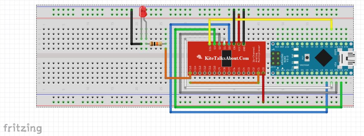
If you have a keen eye you’ll notice analog pin#0 is connected to analog pin #15, which connects to an led. This is done for ease of use, as the example input & output sketches use these pins. Uploading the muxOut file & opening the serial monitor will have the led flash when the counter is between numbers 9 & 15 and deactivate for counter numbers 1-8 & 15-20. After 20 the counter resets to zero and repeats the process.
Example file muxIn is simple in that it just detects the analog value on analog pin #0 and flashes an led if the value is over 1K. I really wish the max detected value of the arduino was over 9 thousand so I could insert a Dragon Ball Z joke, but alas I am not that fortunate. The values are determined by the voltage detected by analog pin#0, connecting 5v always gives the max detected value of 1023, triggering the led flash sequence.
With this completed, you now have the necessary files and verification to prove both mux units operate correctly! Congratulations buddy!