In this post I spoke about using the MCP23017 to increase your digital GPIO ports from 11 to 27, which was remarkable in and of itself, but pales in comparison to what I’ve recently found. Instead of a simple 27 GPIO’s, how about we increase it to a hefty 139 arduino ports? All we must do is make a few changes to the previous code used in the Adding Arduino Digital/ Analog Ports post from before.
Required Items:
Analog Mux Digital Mux(x8) Digital Mux Adapter(x8)
In case you haven’t already, be sure to download the library and point to it via the Arduino IDE with this link:
Private File - Access Forbidden
Once everything is installed navigate to Adafruit-MCP23017-Arduino-Library-master.zip\Adafruit-MCP23017-Arduino-Library-master\examples\multiMux & you’ll be presented with the reference file below:
This is a lot different than the file from before as there is now a total of 8 MCP instances called in the entire sketch, but before hooking everything up, let’s understand a few things.
MCP 23017 I2C Protocol
The digital multiplexer works via the I2C protocol, which uses a serial clock and serial data to transmit data from multiple devices using device addresses. Without these two lines the entire project woudn’t work & we’d have to resort to other means.
Anyway, the last step in understanding configuration is how you configure the MCP’s address to work over the I2C protocol.
Addressing is done by a combination of setting pins high or low, but before we get to that, let’s first understand the pins in the MCP & how they work using the reference chart below:
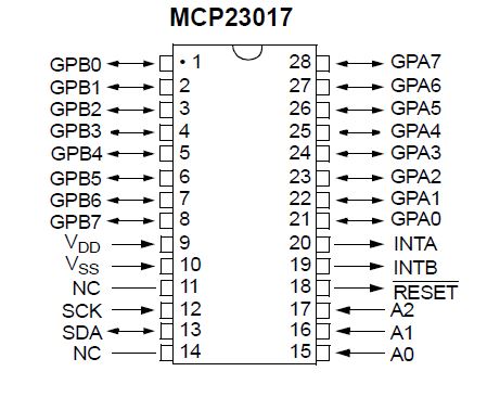
Going from bottom right to top right, then top left to bottom left we will be covering the important pins you need to know & skipping the unnecessary ones. We’ll be using two terms in this instance, physical pins & mux pins. Looking at the diagram, physical pins are only the numbered pins, while mux pins are the varied pins, such as A0, INTA, or Vss.
Physical pins15-17, are the addressing pins you connect to either ground or 5 volts depending on the number of MCP’s you have & your personal preference. Though we will be using all addresses for this tutorial, note that when using less than the maximum, you’re able to dictate the address of each chip & what it does. Pins 21-8 are GPIO pins that can only digital read/write from 16 pins starting with physical pin 21 as mux pin 0 through physical pin 8 as mux pin 15. This number increases as you go counter clockwise to physical pin 8. Mux pins VDD & VSS are the VCC & ground connections, respectively, & power the chip. Lastly are the mux SCK & SDA pins, which connect to A5 & A4 respectively.
Now that we have that, let’s refer to the pinout & address chart to understand how everything connects:
| MCP Pinout Chart | |||
|---|---|---|---|
| Arduino Pin | Mux Pin | ||
| ??? | A0-A2, Check Address Chart | ||
| 5V Thru 10k Resistor | Reset | ||
| 5v | VDD | ||
| Ground | VSS | ||
| A5 | SCK | ||
| A4 | SDA | ||
The MCP number refers to the number in parenthesis in mcp.begin(0). The zero tells the program to start the digital port expander with address 000 as HIGH equals 1 & LOW equals zero. If you don’t plan on using all 8 slots for your port expander, you can decide which expander uses what address.
| MCP Address Pinout | |||
|---|---|---|---|
| MCP # | A0 | A1 | A2 |
| 0 | LOW | LOW | LOW |
| 1 | HIGH | LOW | LOW |
| 2 | LOW | HIGH | LOW |
| 3 | HIGH | HIGH | LOW |
| 4 | LOW | LOW | HIGH |
| 5 | HIGH | LOW | HIGH |
| 6 | LOW | HIGH | HIGH |
| 7 | HIGH | HIGH | HIGH |
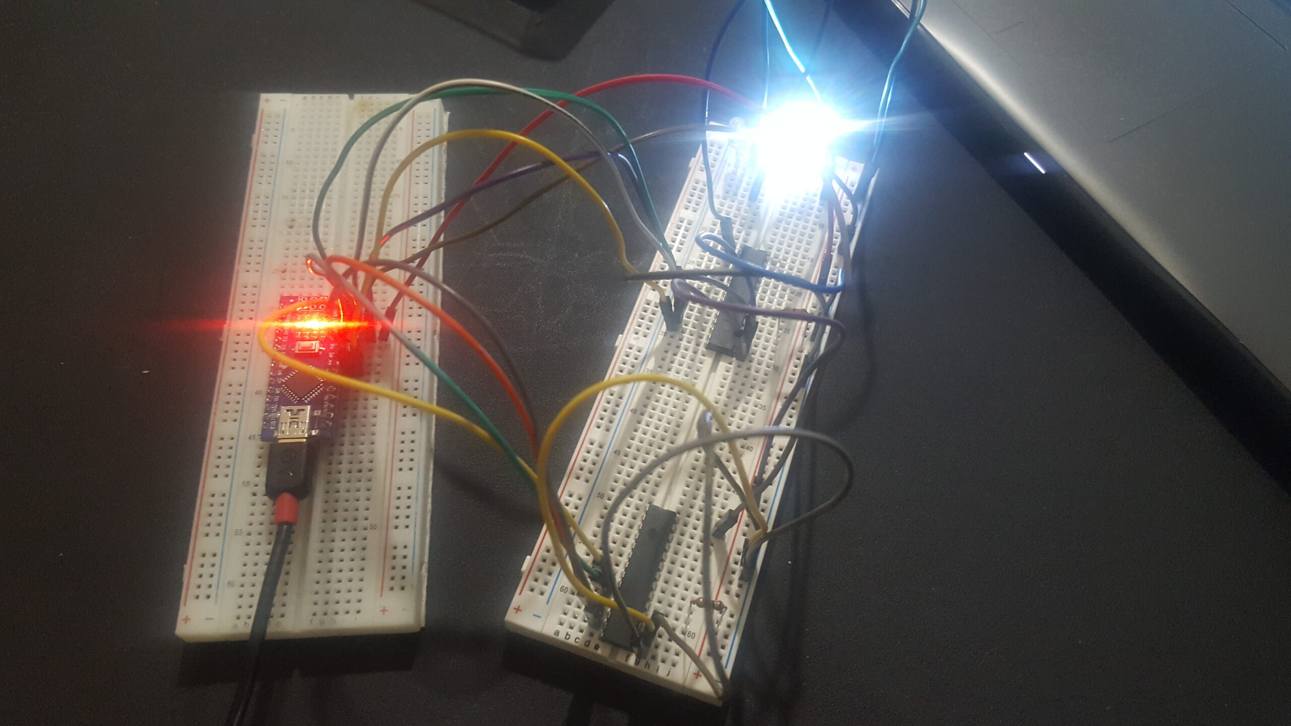
Once everything is connected & uploaded, you will now have the capability to power many items such as fans, relays, I2C LCD’s & more.
I had the worst time figuring out how to connect multiple MCP’s as not a lot of folks seemed to use it when I checked YouTube and other social media platforms. I only happened upon a few articles that explained how to operate it with the library I was using & even then, my own stupidity got in the way. For about an hour & a half I could only get the first MCP working while the second one acted as if it were I dud. I constantly checked my wiring & the diagram, ensuring everything was perfect just for it to still not work. After a while a random thought passed me, “What if I’m using the wrong chip?”
At first I scoffed as I only use the ATMega chip & the MCP chips & they’re separated so that would be impossible.
….I paused….
Wait.. what if it was the wrong chip? They look exactly alike save for the nearly invisible label on the MCP & the bold lettering of the ATMega. It’d be so easy to mix them up & not know about it! So I peeked at the label & saw bold lettering….it was an ATMega chip. I howled in laughter at my mistake, replacing the chip with the correct one. Once replaced, everything worked perfectly & I shook my head for my own stupidity.
Now What?
With everything hooked up, my next step is to have a unified system that operates all my pet enclosures from one microcontroller. Generic arduinos are four bucks a piece, which is cheap until you scale it up to 10+ units compared to operating with just one or two units. There are still a few components needed outside of the ones I spoke of to get everything working right, but if my package comes in sometime today I’ll start working on this unification. The only pain I have to deal with is running all those wires as I did for Kimah & Lora. Stay tuned as I’ll soon have another article up explaining a few more components.