The ATTiny84 is a smaller µcontroller I purchased as a replacement for the ATMega328-pu circuit, a favored but unnecessary circuit to have for simple applications. After a bit of online research & hearing the tutorials from many different YouTubers & outdated websites, I’ve decided to make my own guide to tell you how I assembled my ATTiny84 µcontroller.
Required Items:
ATTiny84 10µF Capacitor 10KΩ Resistor Single Color LED Elegoo Uno Chip Socket
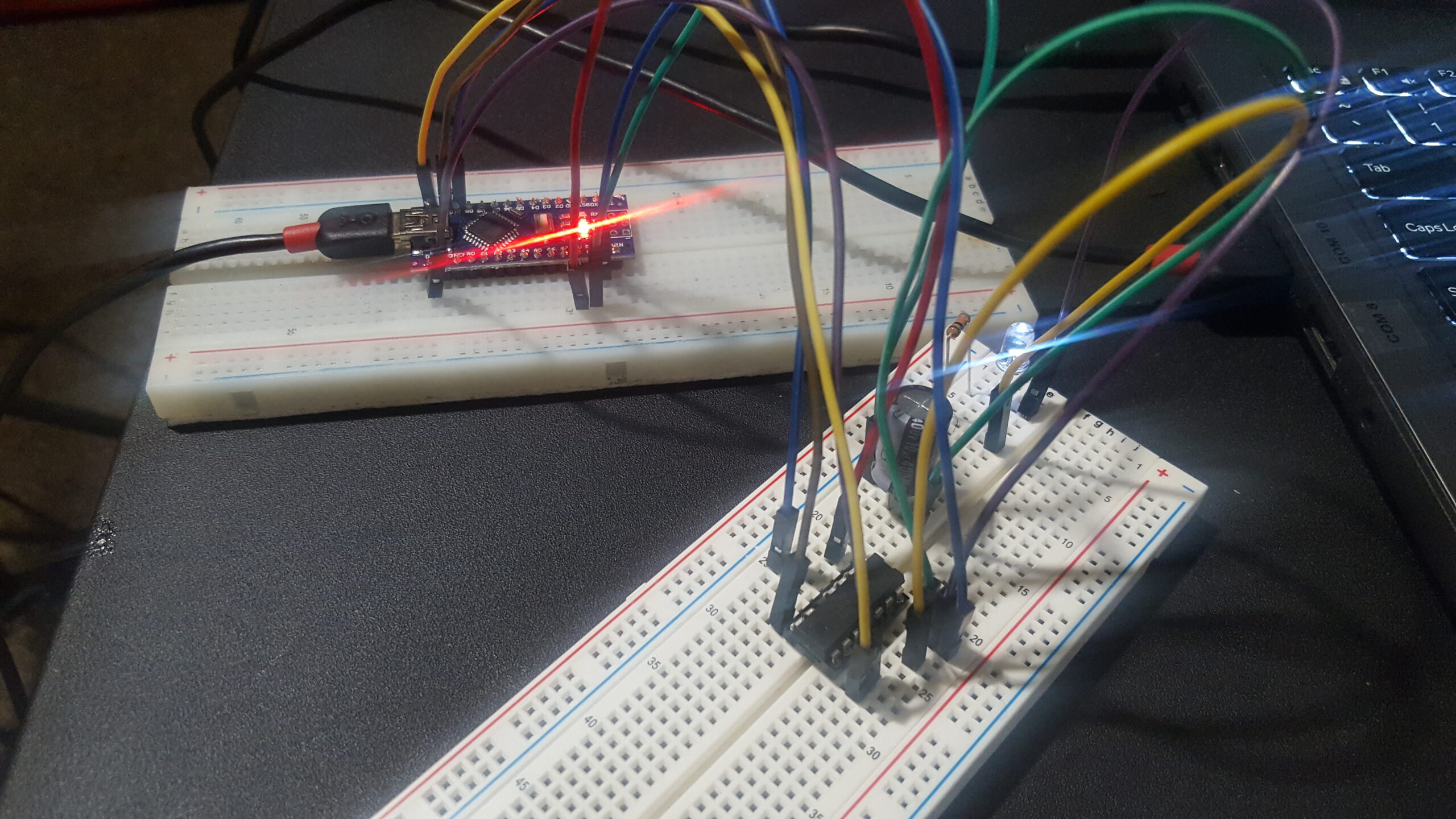
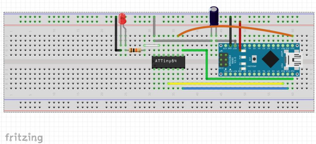
Fritzing Sketch
In this demonstration we’ll be doing the usual blink sketch as a quick way to acquaint you with the chip. I opted for the ATTiny 84 as it has eleven GPIOs as opposed to the ATTiny 85’s 8. Its a simple chip for simple tasks as its storage is 8kb as opposed to the ATMega’s 32K of flash. What it lacks for in pins & memory it makes up for in affordability being that its $1 as opposed to the ATMega’s $4, making it perfect for small projects needing to fit in small spaces.
Pinout Illustration
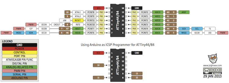
Above are two diagrams depicting the 84’s pinout as well as how it needs to be connected. Despite the illustration I’ve supplemented it with a pinout chart showing exactly where everything goes since the chart doesn’t show a hookup for the reset pin of the arduino, which would derail the entire project. Note that the ATTiny pins in the chart reference the white numbers on the chip itself & not any other pins as some may believe.
ATTiny84 Pinout Chart
| ATTiny84 Pinout | |||
|---|---|---|---|
| ATTiny Pin | Arduino Pin | ||
| 1 | VCC | ||
| 4 | 10 | ||
| 7 | 11 | ||
| 8 | 12 | ||
| 9 | 13 | ||
| 14 | GND | ||
| 14 | RESET(RST) Thru 10 uF Capacitor | ||
Software Setup
If you haven’t already, go to the Arduino website to download the latest software as the ATTiny operates on the latest sketch versions according to my research. You DO NOT need to download a legacy Arduino IDE by any means. Note that the hardware is to be connected as described above with the exception of the ground wire to the 84, as its to be disconnected until final verification to ensure nothing is accidentally damaged. Once the ground wire is disconnected complete the following:
- Navigate to File> Preferences
- In the Additional Boards Manager URL: Input the following: https://raw.githubusercontent.com/damellis/attiny/ide-1.6.x-boards-manager/package_damellis_attiny_index.json. This is the reference the IDE will use to retrieve board information for every ATTiny board type, not just the 84.
- Go to Tools> Boards> Board Manager & lookup Attiny, a download file will pop up automatically for you to install the files in the IDE.
- In File> Examples> Arduino ISP (In serial programmer) select the file and upload it as you normally would by verifying you’re using the correct board type, programmer, COM line, & processor type.
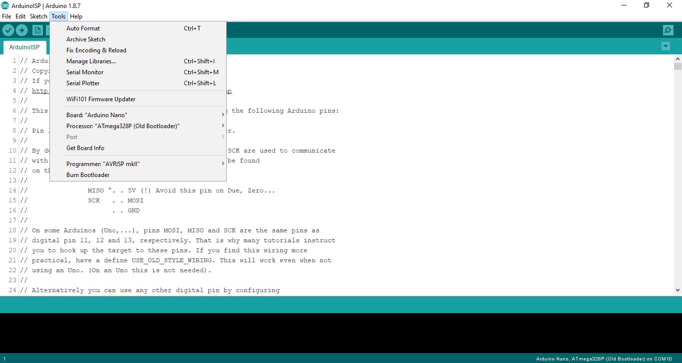
5. After upload is complete, change your tool settings so that Board: ATtiny24/44/84, Processor: ATtiny84, Clock: Internal
1 MHz, Programmer: Arduino as ISP. Look at the screenshot below for verification.
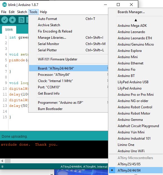
I can’t stress enough the importance of ensuring the above is EXACTLY as described or you will brick (irreversibly damage) your IC as I’ve accidentally done. I also thought to input the clock as 8MHz as described in the ATTiny’s description. Guess what? Bricked another one doing that, so 1MHz internal at all times.
6. Connect the ground wire & upload the blink code as seen below, upload, & you are done!
What Now?
As stated before, the 85 is like all other ATTiny’s in that there are limitations to what it can do. The supported commands, borrowed from Instructables are as follows:
pinMode()
digitalWrite()
digitalRead()
analogRead()
analogWrite()
shiftOut()
pulseIn()
millis()
micros()
delay()
delayMicroseconds()
With such limited support, why use it? Well, the 85 is useful in that low powered projects are perfect for it. I’m going to use it for my gardening project as a soil moisture sensor. When the average moisture level gets to a certain point it will send a high signal to an ATMega, which will request water from a reservoir in my house. I’ll have a discussion about my indoor gardening project, just note that its development is in the works. Currently, I plan to have the 85 as a door alarm in my pet room to remind me to close the door so that I don’t get an escapee like when Lora escaped her cage a few weeks ago.
For now, I hope you liked these simple & easy to understand instructions on programming the ATTiny 85 microcontroller.