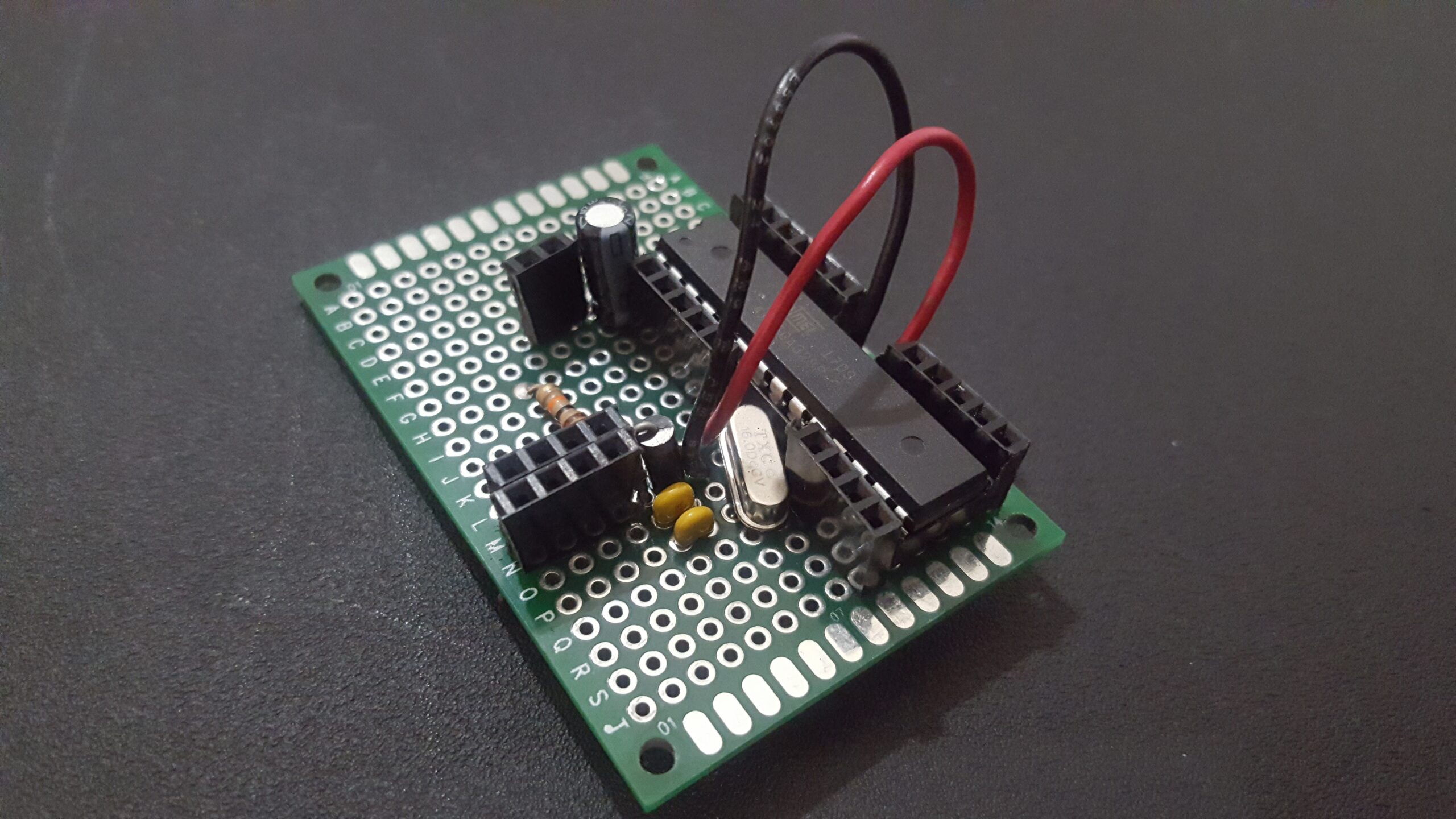
Making the stand alone arduino is a great way to learn more about the µcontroller (microcontroller) that powers the official Arduino µcontroller as its the brains that controls all the inputs & outputs, data processing, etc. of the controller. While using an official Arduino (the capitalized ‘a’) or clone is useful, the experience isn’t the same as building, programming, & completing your own. An official Arduino costs $22, a clone costs $10, which is cheaper, but doesn’t compare to the $4 expense needed to assemble your own. An added benefit is that the chip is an easy $2 replacement if you happen to burn it out, which will happen often as you start your arduino journey.
Required Items:
22pFCeramic Capacitors ATMega328-P 10KΩ Resistor ATMega328-P Socket 16MHzOscillator 100µFCapacitor Elegoo Uno Diode Female Header Bread board Elegoo Uno 100ΩResistor
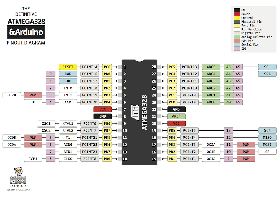
The reference diagram below shows all the pins of the ATMega board & will be a staple reference point as we build our stand alone arduino. The white numbers on the chip will be referenced as pins while the numbers in the purple box will be referenced as pinouts. The difference between the two is that ‘pins’ will primarily be used to build the unit, while pinouts will be called in the IDE for data processing & data input/output.
Programming The ATMega
Before we can flash leds or program an automated drone, we first have to program the ATMega so it knows how to process data by using the Elegoo Uno as an in system programmer, or ISP. The uno’s built in FTDI chip will be used to program & reprogram the ATMega, but we will discuss this further soon. For now, you need to set up the uno as an ISP & will do so by connecting the uno to your computer & selecting the necessary COM port, programmer type (AVRISP mkII), & board type (Arduino/Genuino Uno). Now, navigate to File>Examples>Arduino as ISP & upload the resulting popup sketch to your board.
The last step is to hookup your ATMega by using the reference Fritzing sketch in conjunction with the chart below:
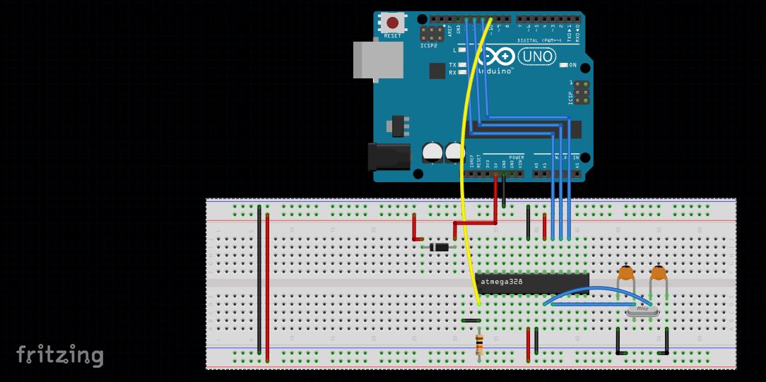
The chart below shows how everything seen in the Fritzing sketch above is to be connected. The ‘Item’ & ‘ATMega Connection’ columns are related in that it describes how each item connects to the ATMega pins while the ‘Arduino (A) to ATMega (AT) Connect.’ column describes how connections are made from the Arduino to the ATMega.
| Item | ATMega Connection | Arduino (A) to ATMega (AT) Connect. |
|---|---|---|
| 22pF Capacitor (1) | Pin 10 & Ground | – |
| 22pF Capacitor (2) | Pin 9 & Ground | – |
| 16MhZ Oscillator | Pin 9 & 10 | – |
| 10KOhm Resistor | Pin 1 & 5v | – |
| 5v | Pins 7 & 20 | 5v (labelled) to bread board vcc (red line) |
| Ground | Pins 8 & 22 | Ground (Labelled) to bread board ground (blue line) |
| Diode | In series to 5V | A (10) to AT (1) |
| – | – | A (11) to AT (17) |
| – | – | A (12) to AT (18) |
| – | – | A (13) to AT (19) |
Double check your work & once certain it’s hooked up correctly go to the Tools> Burn Bootloader tab. You should see the arduino lights flicker quickly for a few seconds & then stop with the IDE saying that the task has been accomplished. You’re halfway done now as the only remaining task is to verify everything operates correctly.
ATMega Verification
With the bootloader uploaded to the ATMega, it will now operate as any arduino would with a few changes:
1. Using a knife (be careful!) or similar tool, remove the chip from the uno board.
2. Remove all wires except the 5v & ground wire. Your new connections will be as follows:
| Item (I) to ATMega (AT) | Arduino (A) to ATMega (AT) |
|---|---|
| 100uF Capacitor (negative leg) to AT (1) |
A (RX) to AT (2) |
| 10K Ohm Resistor from 5v to + lead of 100 uF Capacitor (No AT connection) |
A (TX) to AT (3) |
| 100 Ohm Resistor to AT (15), other resistor leg to positive (long leg of led) |
A (Reset) to positive lead of 100uF capacitor (no AT connection) |
| Short leg of led to ground | – |
3. Your new IDE settings will be Board: (Duemilanove or Diecimila), Processor: ATMega328P
The Fritzing sketch below shows how everything is supposed to look:
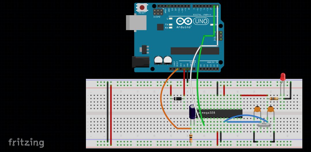
Upload this code to the ATMega, when it works, congrats, you’ve gained another skill!
Next Post: AtTiny 84, Arduino’s Little Brother Next Post: Creating The 139 Pin Arduino