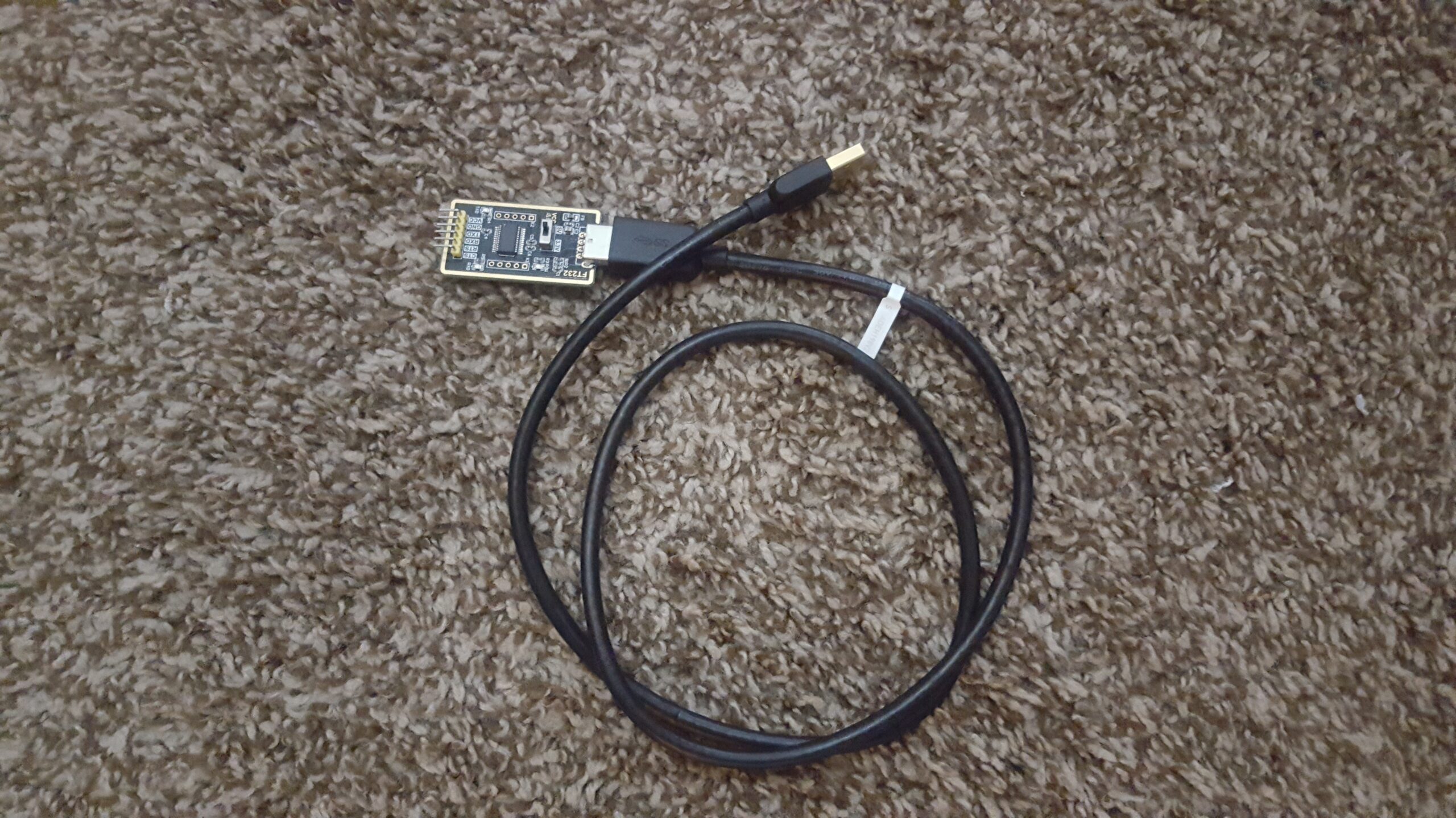
Check Out Our Other Arduino Based Posts![/su_button]After a lot of inspecting, making, remaking my ATMega units, I’ve come to the conclusion that the issue isn’t with my ability to make them, but the FTDI programmer I’m using. I used to use this one, but as its description says, its not a genuine FTDI, so my computer likely bricked it. I bought a second one to ensure I didn’t just get a bad unit, but the replacement even stopped working. Perhaps there’s a variable I’m unaware of, but to be on the safe side I bought a genuine FTDI programmer & received it today with stunning success. Its capable of plug & play, & can program with 3.3v as well as 5v.
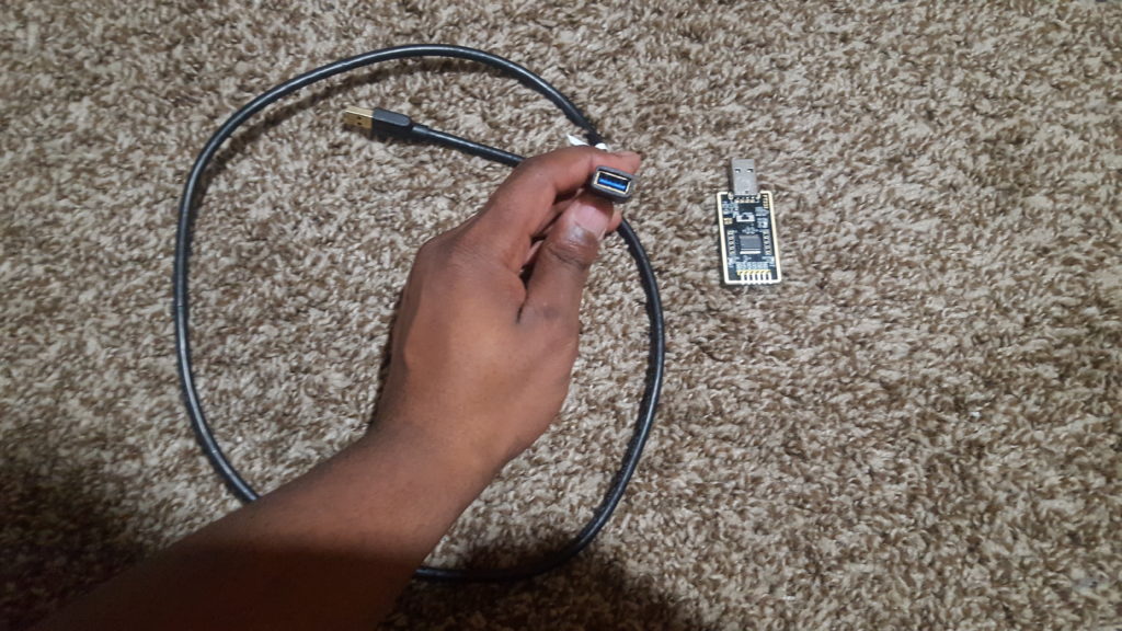
There are some gripes I have with the unit, one of which being that you need a M/F USB cord as the FTDI has a male connector instead of the usual female. Its weird, but is a small issue compared to how useful it is. A working FTDI means I can take the next step in my programming ventures by having a plug & play programmer to program my ATMegas. The picture below shows what I mean. I dislike having to make the pin connections, so for this ancient ATMega setup I used wires & make header pins to make it for me. A modern iteration of this setup is in the works for future use, but with major changes. Here are the public highlights:
1. No Visible Wiring
Beyond the unavoidable 5v & ground wires, the rest of the wires seen here will be under the board & away from sight. If they have to cross each other they will likely be insulated using clear nail polish, which I know is weird for me to say, but it works. I’ve used it to insulate electronics buried underground with no rust in sight, so wires used above ground should have no issue.
2. No linear regulator
All early ATMega units featured a linear regulator that took a 12vdc input & lowered it to the 5v limit of the chip. It certainly served its purpose but made the board clunky, requiring me to change it by replacing it with a buck converter. This convertor drops the voltage just like a linear voltage regulator, but adjusts it to any voltage lower than the input. This saves a lot of board space & is simply cheaper.
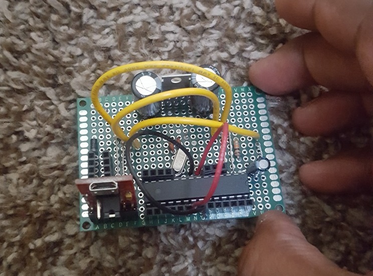
3. New Board
The biggest change is replacing the ATMega rig altogether as I’ve found a more condensed & cheaper board that’s still as robust as the ATMega. The ATMegas that I have will still be used in projects as I dislike wasting money, but the FTDI mount will be implemented with both boards. I’ll wait until I receive the boards before I make it all public, but I am excited to see how this project turns out as I anticipate it’ll be a success. Time will tell, but here’s to crossing all fingers & toes!
Making Your Own Arduino Creating The 139 Pin Arduino