Within the RF realm, filters are used to reject undesired signals when monitoring the spectrum environment. Maybe you’re in an urban area and your neighborhood is right next to an FM tower, or you happen to live next to an Army Signal Corps antenna nerd who does home experiments where he stomps over other signals with his home made radio that runs off a generator, significantly raising the local noise floor. Weird coincidence, right? But you need to do something about it, ergo– use a filter!
But What Kind?
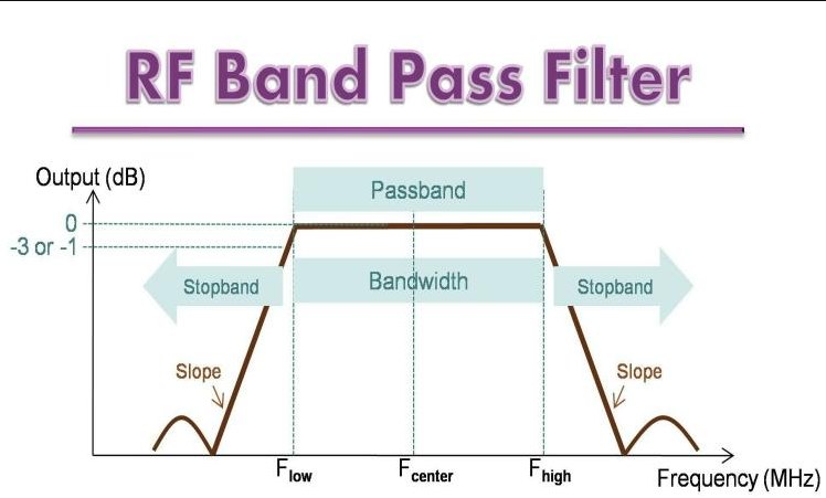
Depends on your use case as there are several types of filters. You have High Pass, Low Pass, Band Pass, and Notch Filters. Low pass filters allow low frequency signals to pass- hence the name- and rejects/ eliminates/ attenuates (all words are the same in execution) higher frequency signals. High pass filters work inversely, allowing high frequencies to pass and rejecting low frequencies. Band pass and notch filters have an inverse relationship as well in that band pass filters allows a specific frequency range and rejects all signals out of the frequency range while a notch filter does the opposite and only eliminates a specific range, allowing all else to pass. The filter you use depends on what you’re trying to do. Going back to the Army guy example, if he’s stomping all over a specific and small signal band it may be better have a notch filter; whereas if there was a larger interference source OR you were analyzing a specific band for regional plane tracking for example, a band pass filter may be better. The TLDR is if its a specific signal you’re looking for or looking to exclude use a notch or band pass filter, if its a wider range of frequencies consider a low or high pass filter.
Signal Boosting
A lot of filters have some type of signal boosting, enhancing a band of frequencies to improve reception, analysis, and/or decoding. These are called LNA’s or (L)ow (N)oise (A)mplifiers, as they increase the dB or power of lower amplitude signals while avoiding noise floor increases. You get what you pay for when purchasing these as some do a great job while others are essentially trash. Be sure to look at reviews and pictures to verify the review isn’t essentially paid for by way of free sample as well as cross reference YouTube.
Caveat
Signal boosting and all the LNAs in the world won’t help you if you have a terrible antenna that can barely receive signals in the first place. This is where antenna knowledge comes in. Specifically knowing your frequency, connection type, dB, encryption/ modulation type, environment and location.
Frequency
Is the amount of cycles a signal completes per unit of time, which is nearly always in seconds. A cycle is defined as a signal having a peak-trough-peak, then repeats for another cycle. The correlation between the amount of cycles per second is called Hertz. So if a signal completes 100 cycles within a second then its frequency is 100 Hertz, which is abbreviated as 100 Hz. Now, Let’s quickly go over measurement standards. In school you learned when describing numbers that you had the tenths, hundredths, thousandths, millionths, billions, and so on; describing Hertz shares much of the same terminology as number places. Use the below image as a reference. Going from right to left and looking at each decimal place as we do you have Hertz (Hz), killoHertz (kHz) (thousands of Hertz), megaHertz (mHz) (millions of Hertz), and gigaHertz (gHz) (billions of Hertz)

To convert a lower value to a higher one and vice versa just add or drop the decimal places, or if you don’t have values displayed as you see in the above graphic add zeros to the front to reduce the value, or to the back to add it. As an example using the graphic we have 854kHz. If we wanted to convert it to hertz we would remove the decimal place- giving us a signal value of 854900 hertz. If the signal value was 854.000 kHz we would change the converted value to 854 Hz.
Connection Type
Though a minor entry, its still a consideration to make when dealing with antennas as they often times come with different connection types. SMA, RP-SMA, BNC, 7/16 DIN, MMCX are a few connection types depending on your use case. A lot of the time you can find adapters to connect one type to another, but do your research to ensure that an adapter exists for your antennas, that its easy to obtain, and that it can be readily accessed by more than one company on your store front of choice such as Amazon and eBay.
dB/ Gain
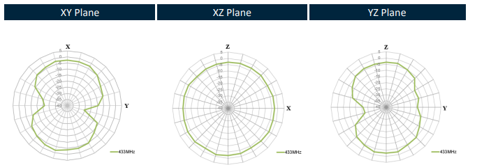
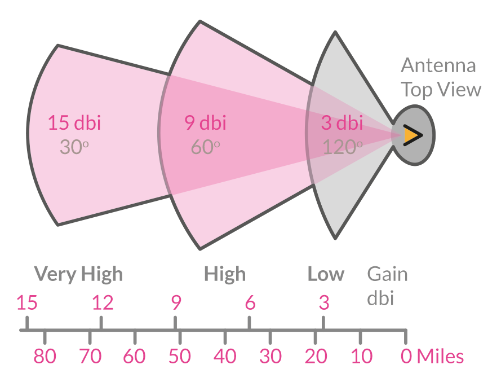
We won’t cover dB math because I said so. But know that gain is related to the distance a signal will travel as well as its directionality. A low gain antenna has a low EIRP Effective Isotropic Radiated Power as seen in the 3dBi graphic, whereas a high EIRP antenna will have a radiation pattern as seen in the 15dBi portion of the picture. A low EIRP antenna is able to reach the distance though not the shape of the 15 dBi one, but it required significantly more power assuming the antenna or radio doesn’t get friend first.
Also note that the graphic is just for the point of showing the radiation pattern of a signal and doesn’t mean the transmission range will be as illustrated. A combination of looking at the label and doing in the field testing is the best way to verify the transmission characteristics of a signal. A lot of antennas come with or feature a chart describing the propagation characteristics as seen below. Here we can see the propagation characteristics are absolute trash and that makes sense considering the dB of the antenna is zero, rendering it worthless for most communication right next to modern day smoke signals. With how low the EIRP is, it functions more like an omni directional antenna than anything. There are many types of antennas, such as yagis, dipoles, helicals and many more. Each with their own signal propagation characteristics, effective ranges, and effective frequency ranges; requiring research to understand the types and their use cases. Next would be polarity. There are vertical, horizontal, and circularly polarized antennas, and describe the method the signal is propagated. For there to be proper communication antennas must be the same polarity and depending on the frequency, distance, and environmental conditions, within line of sight of each other.