The DS18B20 is a waterproof temperature sensor capable of being used for an automated aquarium, terrarium, or any environment in which the DHT22 cannot be deployed due to rust or other damage susceptibility. While DHT22’s are very accurate and give a variety of data such as humidity, heat index, etcetera, the problem is that it’s incapable of being protected from corrosion. This tutorial explains how to hookup, code, and deploy the DS18B20 waterproof temperature sensor.
Required Materials:
Bread Board DS18B20 Elegoo Nano Male Dupont Pins Dupont Wire Covers
Jumper Wires 10KΩ Resistor Wire Stripper Soldering Equipment
Library:
Private File - Access Forbidden
Fritzing Sketch:
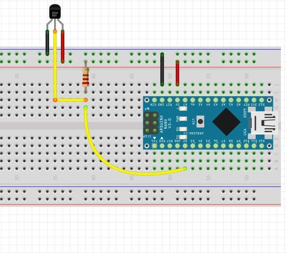
Physical Depiction:
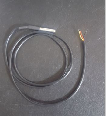
Comparing the Fritzing sketch to the physical depiction, its obvious there’s some inconsistency here, but the sensor seen in the Fritzing sketch is inside the silver color housing in the physical depiction. The wire length ensures enough space is given to immerse the unit in water or otherwise have it spaced away from the Arduino its connected to. Note that the data pin of the DS18B20 is connected to a 1KΩ pull up resistor, with another pin connected from the pull up resistor to digital pin two of the micro-controller. Though any digital pin can be used, note that the unit will present inconsistent readings if the data line configuration doesn’t reflect what’s in the sketch, so take care as you’re wiring. Take care when removing the wire insulation from the red/yellow/black wires as the bare wire is low gauge and easy to damage. To combat this I twist the wire and solder it using male dupont pins and wire covers to avoid shorting out from bare metal contact.
Once the hardware is assembled, navigate to the sensor’s library and include it in the IDE using [1] How to include an arduino library this link if you need a refresher. Once you have it downloaded you don’t need to move any files around as its provided in the document viewer below. Now, the hexadecimal address of the DS18B20 must be retrieved for proper pin assignment in the IDE. The DS18B20 is able to have multiple sensors connected on a one wire bus as well as retrieve multiple addresses at the same time, but an inability to distinguish which address is assigned to what sensor makes this extremely difficult. This is why address retrieval will be done one at a time. Once you have everything hooked up, verify you’re using the proper COM port, copy/paste the address finder code, then upload.
DS18B20 Address Finder:
Once everything is uploaded, open the serial monitor in the IDE menu by selecting the Tools> Serial Monitor and you will see the hexadecimal address of the connected sensor. Record it on a digital notepad and connect the next sensor if desired, repeating the same process. Note that if you prefer using a different digital pin that you must change the number in ‘OneWire ds(2)’ to the appropriate pin. Now that we’ve completed the retrieval process, let’s put the sensor to work with a test run.
Copy/paste the code below into a new sketchpad, ensuring that you replace the hexadecimal address listed with the one you retrieved. The ‘reservoir1’ name can be changed to whatever identifier you choose as long as you ensure the name change happens in the loop section of the code as well. Lastly, the “Serial.println(“Initiating DS18B20 Protocol”);” text can be changed as its not vital to code execution.
DS18B20 Execution Code:
If everything is connected correctly then you should receive a temperature reading, thus marking the completion of the test run.