After building projects for your home, you’ll eventually want to take your progress to the next level and install them outside your house. Maybe to monitor an outdoor garden or a DIY barn temperature sensor to know when the horses need their blankets on. Accomplishing this requires a battery, and though there are many out there, one that I recommend is a LiPo, or Lithium Polymer battery. So in this tutorial I’ll not only teach you how to power your arduino via LiPo battery, I’ll also show you how to detect the battery’s voltage level and how to charge it.
Required Items:
100kΩ Resistor(x2) 2s Lipo Battery 10kΩ Resistor(x2) Multimeter Lipo Battery Checker
Fritzing Sketch:
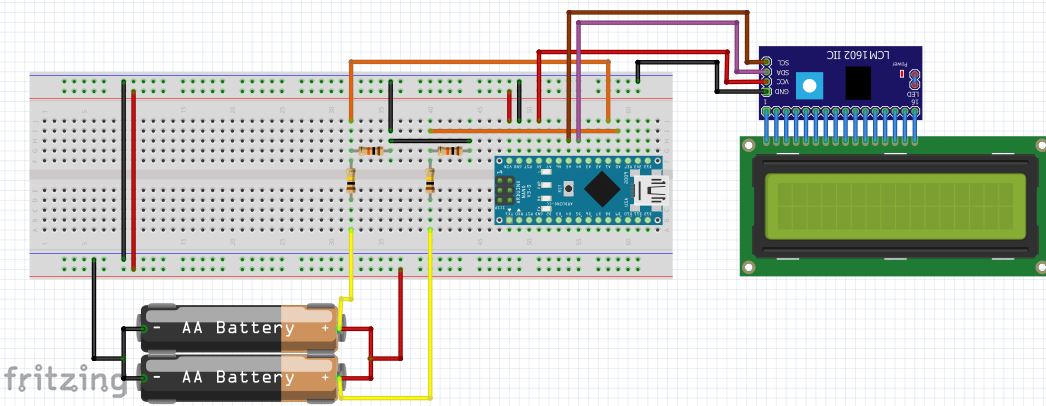
The Fritzing sketch shows alkaline batteries as the power source for this project, but it is just a stand in for LiPo batteries as none could be found for the software I’m using. Also concerning the batteries are the red and yellow wires connecting to the positive rail and Arduino volt meter respectively, these too are stand ins for the depiction shown below. Using the Fritzing sketch as a reference and comparing it to the physical depiction, you see the black ground wire for the balance charger terminal and for power wire have been combined as a single wire for convenience’s sake.
Lipo Battery Physical Depiction:
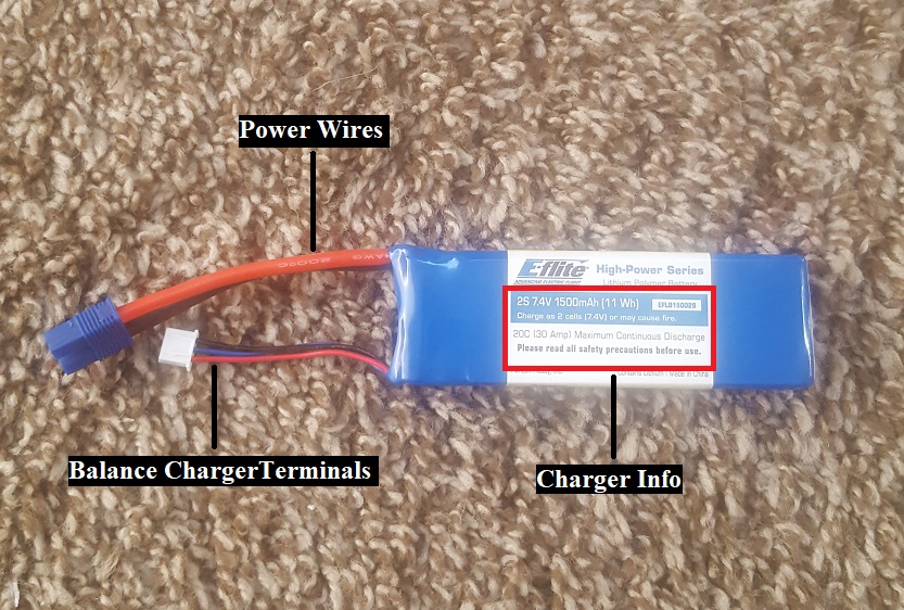
The balance charger is used by the charge unit to ensure multi cell batteries are all charged to the optimum voltage of 4.2V. Without this balance charger, there’s a high risk of cells being over/under charged, which can lead to violent ignition of the battery. The balance leads communicate the voltage of each individual cell with a common ground to complete the circuit, cell one being left of the ground wire and cell two being to the left of cell one. Being that the cells are connected in series, the voltage will increase by 4.2V (the full voltage value) for each battery added. With the maximum detectable voltage being 30V, the highest lipo unit we can purchase is a 7s lipo (which at 29.4V cuts it extremely close).
Resistance/ Voltage Check
Before connecting anything, we need to use the multimeter to calculate the resistance of each resistor, this is vital when coding the formula to calculate the battery voltages. Turning the multimeter to detect Ohms (the ‘Ω’ symbol) place the red lead on one resistor leg and the black lead on the other. Keep it there for a few seconds as the resistance value stabilizes and record the value once it has. What you want to do is see if there is a difference between the resistance values of both 10KΩ resistors and 100KΩ resistors. If there is then get the average between them and place that number in Line 9 for the 100KΩ and/or Line 10 for the 10KΩ. Next, copy/paste the following sketch in your IDE, ensuring you remove the ‘+.65’ in Line 33 and the ‘+.31’ in Line 34 as those are adjusted values I input to account for the voltage drop when powering the Arduino. Also place the ‘/*’ character on Line 42 and a ‘*/’ on Line 50 without the quotes.
Next, use the preassembled battery checker and record the voltage values it detects, being sure to connect the negative lead with the negative symbol on the back of the checker, this will be your baseline.
Now, using the Fritzing sketch as reference, connect all hardware except the battery power wires. Note that the 10KΩ and 100KΩ resistor must be connected in a specific order to avoid frying the Arduino board. The 100KΩ resistor is where the balance terminal connects to, while the 10KΩ resistor connects to the ground of the Arduino. The point between the 100KΩ and 10KΩ resistors are where we connect a wire to any analog pin except pins A4 and A5 as they are being used by the I2C LCD.
At this point, I remove the USB cord from the Arduino and carefully connect the power wires as seen in the Fritzing sketch, ground being connected first. Now record the values of cell one and two and find the difference between the value you just recorded and the value displayed by the preassembled battery sensor. We will add the difference to the cells to account for this voltage drop by adding the adjusted value to cell one on Line 33 and adding cell two’s value to Line 34. Remove the /* */ characters from Lines 42 and 50 and upload, comparing the results with the reading on the preassembled voltmeter.
Now that you’ve verified it works, ensure the voltage doesn’t fall at or below 3.0 volts per cell or else there could be trouble.
Recharging The LiPo
To recharge your battery, power the charger and it will automatically activate. Short press the Start/Enter key and the xS will flash (x being a number). Assuming you purchased the battery in the required materials section, press the ‘Inc.’ (Increment) button until it says ‘2S’ for a two cell battery, then complete the following:
- Tab over until you see “LiPo BAL-CHG”.
- Press Start/Enter button.
- Adjust the mAh setting until it displays 1700mAh.
- Press Start/Enter button.
- Adjust the charge rate until it says 1.0A.
- Press Start/Enter button.
- Connect the balance charger, ensuring you connect the negative into the correct slot.
- Connect the power cord to the charger, connecting negative to negative and positive to positive.
- Long press the Start/Enter Key
- Watch it as it charges.